Purpose:
Show reverse camera view on my factory 7" screen on my 2009 Pathfinder. Also allow the option to view the camera while driving forward (just in case I want to double check the hitch connections while pulling my trailer).
My Background and how I figured it out:
I'm a Canadian professional Electrical Engineer doing electronics systems design and programming for about 14 years. I used the wiring diagrams and connector pinouts in the factory service manual to figure out exactly where to make connections to the main AV Control Unit.
Result:
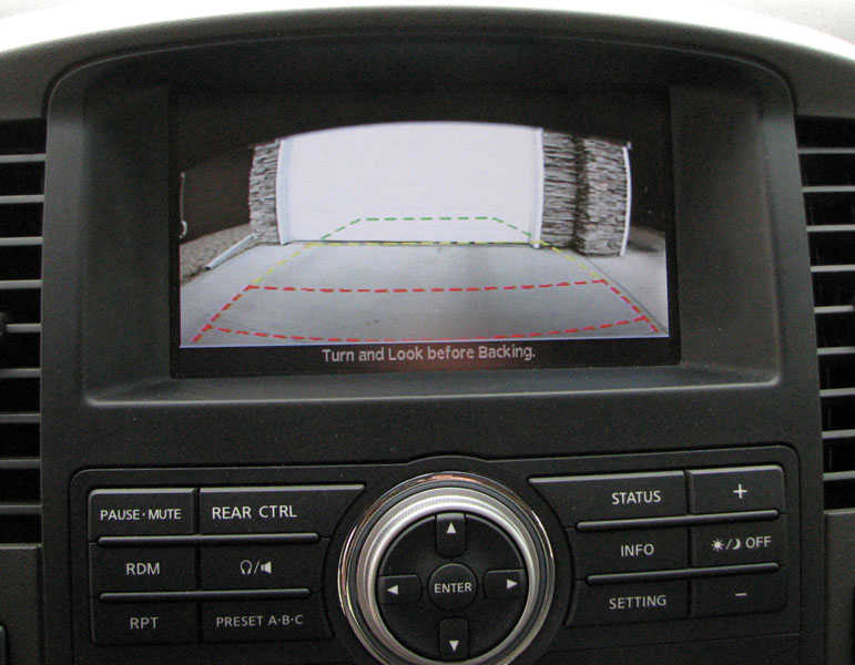
The final product.
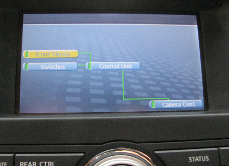
The Diagnostics Screen shows the AV Control Unit is fooled into thinking there is an actual Camera module connected.
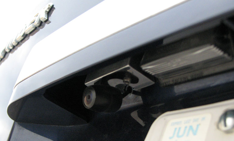
Here is the camera mounted above the license plate (with custom aluminum mounting bracket).
Disclaimer:
The process involved here is not for everyone. I'm not saying that everyone should attempt this hack, I'm simply pointing out how I did it to the best of my knowledge. I shall not be held responsible if anyone damages their system by attempting what I've done.
Process:
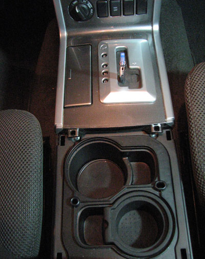
To dismantle the center console, first remove cover around drink holder.
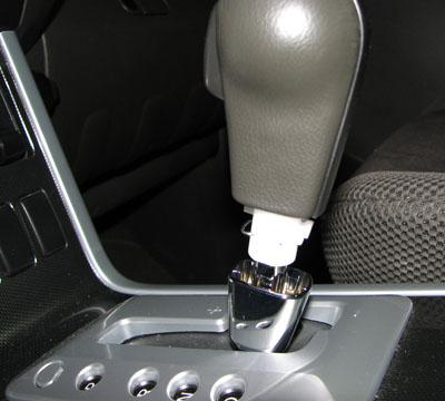
Then remove the gear-shift knob.
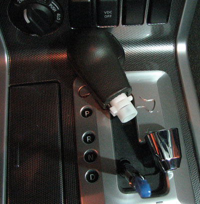
Then remove the gear-shift cover.
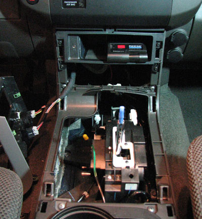
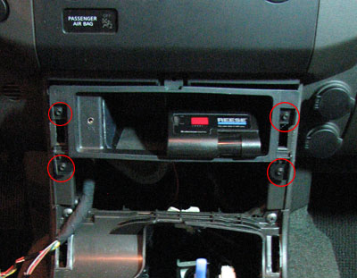
Then remove these 4 screws to pull out the storage compartment.
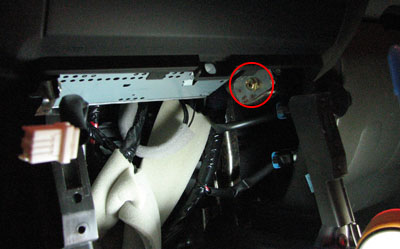
Above the storage compartment are two hidden Philips head screws. Remove them.
Grab the moulding around the top of the screen and give it a good tug to pull off the main AV Control Unit.
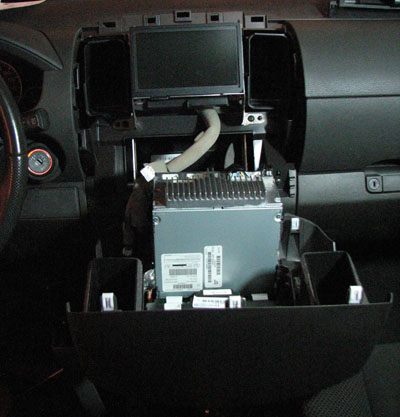
Disconnect all connections from back of main unit and tip it down. Remove these 4 screws.
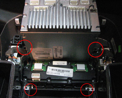
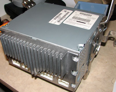
Take the main AV Control Unit to a workbench.
Here is my simple schematic for the connections:
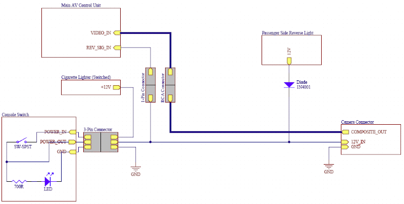
Note that the 1N4001 diode and connection to the REV_SIG_IN is not required. As I said, I only added that to allow me to show the camera while I am driving.
Remove the back heatsink and cover.
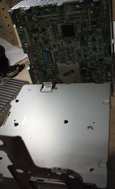
Disconnect ribbon cable to remove top circuit board.
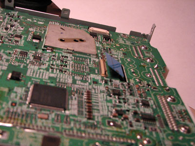
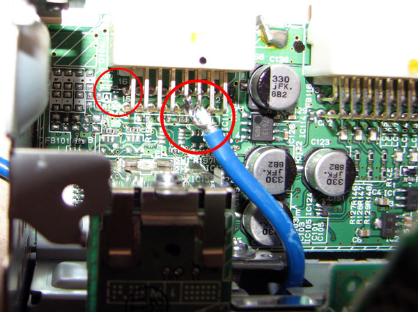
The connector labelled M46 in the service manual needs to have terminal 68 shorted to ground to fool it into thinking there is a factory camera module connected. Terminal 68 translates to pin 16 of the connector on the lower PCB. If I had the proper 16-pin connector kicking around, I would have made this connection outside the PCB. I didn't, so I soldered a very short piece of wire between ground and the required pin on the PCB.
It also shows where I connected the RCA input connector for the video signal. Terminal 65 is the camera+ and terminal 64 is the camera- signal. Refer to page AV-114 in the service manual for these connections.
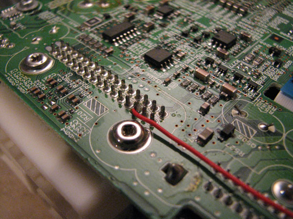
Soldering Reverse turn-on wire to PCB. Note that you probably don't need to add this wire. The AV Control Unit already knows when the vehicle is in Reverse (CAN bus signal or something). The reason I added it was so that I could switch on the camera while driving forward. When this wire is connected to +12V, the screen will show the camera.
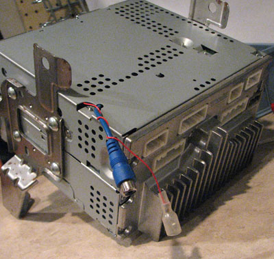
Now that the AV Control Unit wiring is complete, re-assemble it all so that it looks something like this.
Mounting and wiring the Camera:
I had to build a little aluminum wedge to allow the camera to be pointed in the proper direction. Other than that, the mounting steps were pretty basic...
Mark and drill holes.
Use some primer paint to cover the exposed steel.
Use a rubber gasket or tiny o-rings on screw holes to create a seal. Also use a grommet or silicone on the wire.
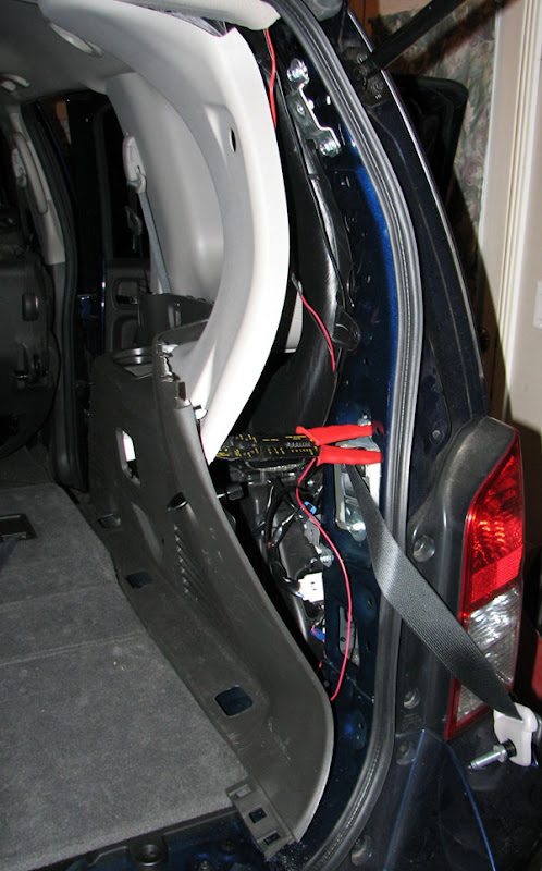
I'm not going to lie here, running the wiring from the camera was not an easy task. This shows the placement of the wiring in the passenger side of the tailgate.
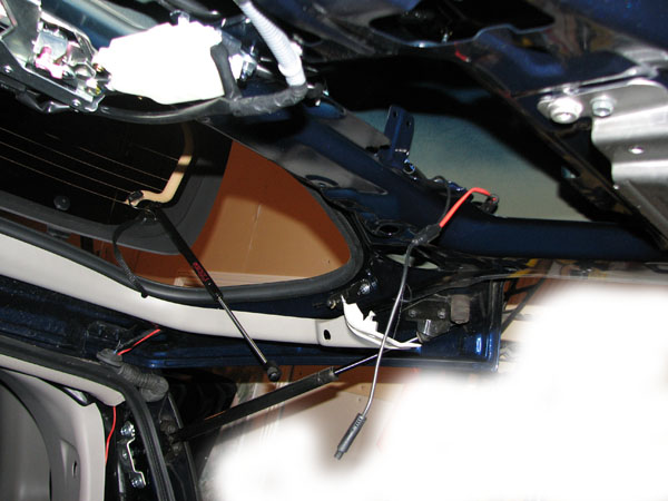
Here is how I ran the wiring down the rear pillar and into the floor.
Further Info:
I purchased a fairly decent quality camera off eBay for $69.99 + shipping. If you are looking for one, search eBay for "SHARP CCD REVERSE COLOR REAR VIEW BACKUP MINI CAMERA". The seller's name is Kazen. Note that it is not actually a CCD sensor (it's CMOS), but it does perform quite well in low-light situations.

It's also nice because you only need to drill a 3/16" hole in the tailgate to pass the wire through. The power wire is run through the video cable which allows for a lot of different options for powering it.
Airbag problem:
If you do happen to turn the ignition ON while you've got the dash apart and the Passenger Airbag light is unplugged, the Airbag system (SRS) will go into a Debug mode flashing the airbag light on the dash. If this happens to you, follow these steps exactly to set it back to User mode (timing is quite critical):
1. Turn ignition switch from OFF to ON.
2. Within 1 second after air bag warning lamp is on for 7 seconds and turns off, turn off the ignition switch.
3. After ignition switch is turned OFF, wait for more than 3 seconds.
4. Repeat steps 1 to 3 two times (Perform 3 times in total.)
5. Turn ignition switch ON again. (Turn to User mode.)
If you've got any questions related to this install, ask away. Otherwise, if you use any of this info, post to the thread and let me know!