Page 1 of 2
PIAA 510 ATP Light Install
Posted: Wed Sep 07, 2011 6:27 am
by GFremont
I purchased pair of PIAA 510 ATPs for my 2008 Pathfinder and I am just about done planning out where and how to do the install.
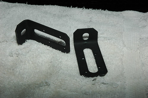
I used some stainless steel carpentry brackets which I cut down and slotted for attaching to the bumper.
I have the harness layout routing figured out but here is the question.
PIAA has a Switched (+) Power lead that is suppose to go from the PIAA supplied switch and splice into a switched power source on the truck.
Any suggestions on a good spot to pick this up? I searched the forums for fog lights but I could not find any details as to where people are tying into the power.
My first thought is to splice into a power wire going to one of the parking lights.
Pictures will come soon.
Thanks.
Posted: Wed Sep 07, 2011 11:23 am
by MonkeyMike
the 12V power to the relay should be fed with a direct FUSED wire from the battery, then from the relay to the light socket. you will need to tap an ignition switched power line somewhere in the truck and run that through your new light switch to the trigger on the relay.
you will NOT want to use the fog/driving light lead as your ignition switched trigger, since these lights turn off when you turn on your brights. i assume you are putting these PIAA's on for off-road use, and therefore would want the ability to run your brights along with these lights.
honestly, i'm not sure what you would tap to ensure you have switched power for the relay trigger. maybe the switched cigarette lighter socket? that would come on with the ignition, and allow you to run the PIAA's with or without your headlights on.
~mike
Posted: Wed Sep 07, 2011 12:10 pm
by GFremont
The set came with the harness and associated relays. I have all that installed and connected. The last is a 12V switched power to control the relays.
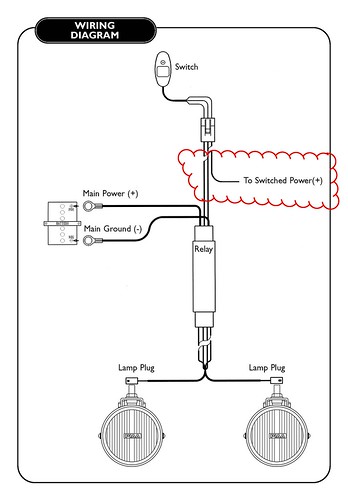 510 Wiring Diagram
 by
Gregg.F, on Flickr
The wire was long enough to route to the front driver's side parking light. I was thinking of tapping into the parking light since I can control that from the steering column and not have to worry about turning on the aux lights without at least having some light on. Also, the parking light is not tied to the Hi/Lo switch that I can tell.
Posted: Wed Sep 07, 2011 2:35 pm
by MonkeyMike
i'm having a mental block right now... as long as the parking lights do not blink with the turn signals, you should be okay using that as the switch power to the relay.
i had forgotten that we have parking lights, and for some reason thought it was only the turnsignals up there.
~mike
Posted: Wed Sep 07, 2011 2:52 pm
by GFremont
I had the same block this morning. I had to go out and check. The blinkers are separate from the parking lights.
Thanks for your comments.
Posted: Wed Sep 07, 2011 4:38 pm
by jspitz
Very cool - the more detail you can provide on the brackets, the better!
Posted: Fri Sep 09, 2011 7:20 am
by HillbillyJake
Maybe I am reading wrong but what you are looking for is a constant power correct. if so you could tap into the plug under the dash for the electric brakes. I believe that is a constant out of the fuse block under the hood. I have 6 led lamps that I am going to mount on my roof basket (4 forward and 2 reverse) and that is where I am planing to get my power from. I know that is what my buddy did in his Titan.
Posted: Fri Sep 09, 2011 10:50 am
by GFremont
I was looking for a switched source to control the relay. The constant power is provided by the battery hookup.
I ended up tapping into the parking light wire. This way I know that if the parking lights are off the fog lights will not inadvertently get turned on.
Once the parking lights are turned on, the switch provided with the PIAA lights is enabled and fogs lights can be turned on and off with the switch.
Even if the the fogs are left on, they will be turned off once the parking lights are turned off.
Sorry for the ramble.
Pictures coming. Just have to get them off my camera.
Posted: Fri Sep 09, 2011 11:32 am
by HillbillyJake
Ok. I follow you know.
Posted: Mon Sep 12, 2011 5:07 pm
by GFremont
Installation Pictures. These are just a few but the rest are on Flickr
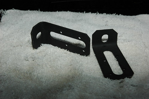
Brackets:
 DSC_3643
 by
Gregg.F, on Flickr
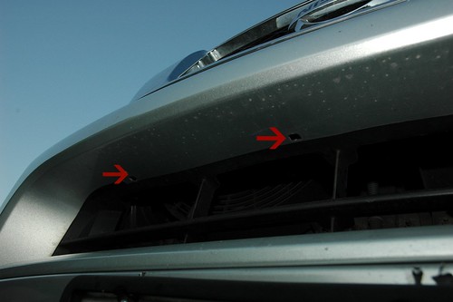
Mounting Holes in Bumper
 DSC_3644
 by
Gregg.F, on Flickr
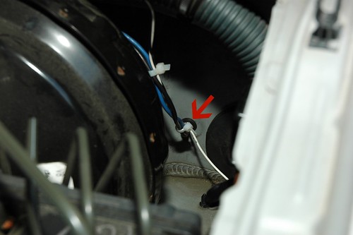
Firewall Feedthrough
 DSC_3656
 by
Gregg.F, on Flickr
Bracket and Light Installed
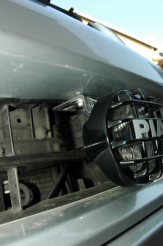 DSC_3668
 by
Gregg.F, on Flickr
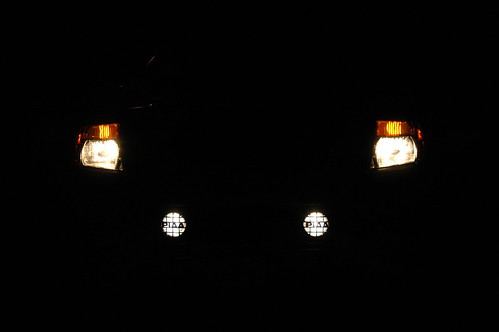
Both Lights Installed
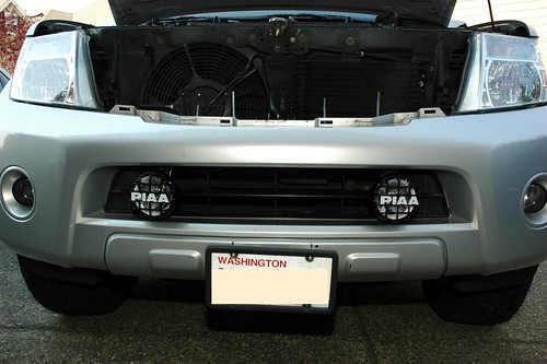 DSC_3667
 by
Gregg.F, on Flickr
Posted: Wed Sep 14, 2011 11:55 am
by GFremont
Some additional photos:
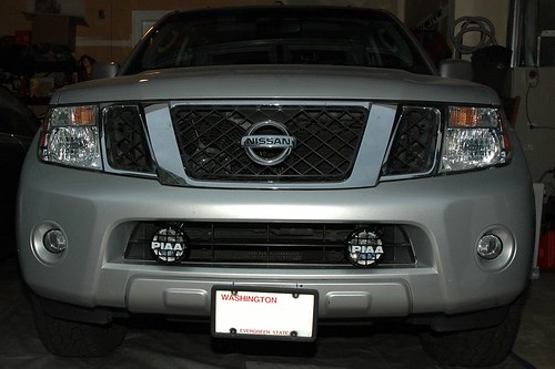 DSC_3683
 by
Gregg.F, on Flickr
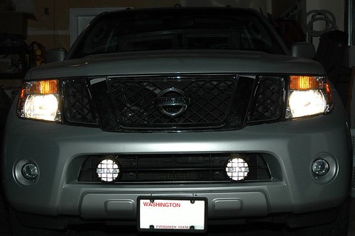 DSC_3682
 by
Gregg.F, on Flickr
 DSC_3676
 by
Gregg.F, on Flickr
I will try to find a decent night to take some photos how well they illuminate what's in front of me.
Posted: Tue Sep 27, 2011 7:52 pm
by slavabon
Nice, clean install. Can you give more detail in the mounting brackets - did you have to bend them and cut them in any way and where did you get them? Thanks!
Posted: Wed Sep 28, 2011 11:30 am
by 05pathyse
Could these be wired to come on with high beams? i was thinking about purchasing some but dont want to switch them on
Posted: Wed Sep 28, 2011 11:49 am
by asgard
I would think this would be very straight forward. If you use a relay with the feed from the battery then you take a feed line from the head light high beam wire and use it th switch the relay.
In line fuse on power in from battery, connection to earth, connection to lights connection to switch high beam. 4 blade lighting relay - check relay rating probably want a 30amp
lamps 2x55 watt = 110 divided by 12 volts = 9.2 amps.
details
http://www.wiringproducts.com/contents/en-us/p3982.html
Posted: Wed Sep 28, 2011 11:58 am
by GFremont
The brackets are made from Simpson A33 Strong Tie stainless steel carpentry brackets. They are already bent.
Here is what I did to complete the brackets:
1. Cut down one leg of the bracket.
2. Add 1/2" dia hole for PIAA light
3. 5/8" dia slot for the mounting bolt to the existing bumper bracket
If I did this again I would make the slot 5/16" or 3/8" wide.
4. Chamfer the corners.
5. Paint them black.
I will post the template I used on the bracket shortly.
The small holes in the picture were already on the bracket when I bought it.
 DSC_3641
 by
Gregg.F, on Flickr